- 您现在的位置:买卖IC网 > Sheet目录1200 > CDB150X-01-Z (Cirrus Logic Inc)DEVELOPMENT BOARD FOR CS1501
�� �
�
�CS1501�
�5.8� Brownout� Protection�
�5.9�
�Overvoltage� Protection�
�V� OVP� =� R� IFB� ?� I� OVP� +� V� DD�
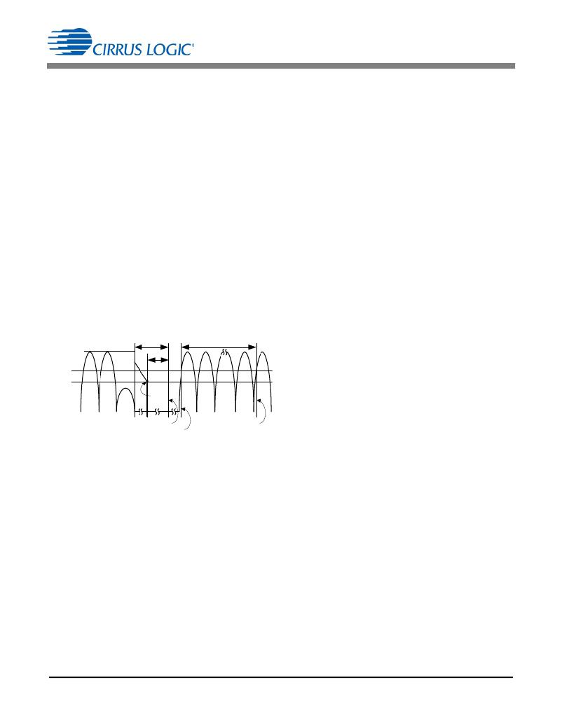
�The� CS1501� brownout� detection� circuit� monitors� the� peak� of�
�the� V� rect� input� voltage� and� disables� the� PWM� switching� when�
�it� drops� below� a� predetermined� threshold.� Hysteresis� and�
�minimum� detection� time� are� provided� to� avoid� brownout�
�detection� during� short� input� transients.� When� brownout� is�
�detected,� the� CS1501� enters� standby� mode.� On� recovery� from�
�brownout,� it� re-enters� normal� operating� mode.�
�Current� I� AC� is� proportional� to� the� AC� input� voltage� V� rect� ,� where�
��page� 11).� The� digitized� current� applied� to� the� IAC� pin� is�
�monitored� by� the� brownout� protection� algorithm.� When� V� rect�
�drops� below� the� brownout-detection� threshold,� the� CS1501�
�triggers� a� timer.� The� IC� asserts� the� brownout� protection� and�
�stops� the� gate-drive� switching� only� if� the� timer� exceeds� 56ms.�
�This� is� the� equivalent� of� 7� rectified� line� cycles� at� 60Hz.�
�During� the� brownout� state,� the� device� continues� monitoring�
�the� input� line� voltage.� The� device� exits� the� brownout� state�
�when� I� AC� exceeds� the� brownout� upper� threshold� for� at� least�
�56ms.� Typical� values� for� the� lower� (I� BP(lower)� )� and� upper�
�(I� BP(upper)� )� brownout� thresholds� are� 31.6� ?� A� and� 39.6� ?� A,�
�respectively.�
�The� overpower� protection� may� activate� prior� to� brownout�
�protection,� depending� on� the� load.�
�The� overvoltage� protection� (OVP)� will� trigger� immediately� and�
�stop� the� gate� drive� when� the� current� into� the� IFB� pin� (I� OVP� )�
�exceeds� 105%� of� the� reference� current� (I� ref� )� value.� The� IC�
�resumes� gate� drive� switching� when� the� measured� current� at� IFB�
�drops� below� I� OVP� –� I� OVP(Hy)� .� Equation� 8� is� used� to� calculate� the�
�OVP� threshold.�
�[Eq.8]�
�5.10� Overcurrent� Protection�
�To� limit� boost� inductor� current� through� the� FET� and� to� prevent�
�boost� inductor� saturation� conditions,� the� CS1501� incorporates�
�a� cycle-by-cycle� peak� inductor� current� limit� circuit� using� an�
�external� shunt� resistor� to� ‘sense’� the� FET� source� current�
�accurately.� The� overcurrent� protection� (OCP)� circuit� is�
�designed� to� monitor� the� current� when� the� active� switch� is�
�turned� on.� The� OCP� circuit� is� enabled� after� the� leading-edge�
�blanking� time� (t� LEB� ).� The� shunt� voltage� is� compared� to� a�
�reference� voltage,� V� cs(th)� ,� to� determine� whether� an�
�overcurrent� condition� exists.� The� OCP� circuit� triggers�
�immediately,� allowing� the� OCP� algorithm� to� turn� off� the� gate�
�driver.�
�The� overcurrent� protection� circuit� is� also� designed� to� monitor�
�T� Brownout�
�56� ms�
�for� a� catastrophic� overcurrent� occurrence� by� sensing� sudden�
�Brownout�
�56� ms�
�and� abnormal� operating� currents.� A� second� OCP� threshold,�
�Thresholds�
�Upper�
�Lower�
�Start�
�Timer�
�V� cs(clamp)� ,� determines� whether� a� severe� overcurrent� condition�
�exists.� This� immediately� turns� off� the� gate� drive,� and� the�
�system� enters� a� restart� mode.� The� CS1501� inhibits� all�
�switching� operations� for� approximately� 1.6ms� then� attempts� to�
�restart� normal� operation.�
�Enter� Standby�
�Start� Timer�
�Figure� 20.� Brownout� Sequence�
�Exit� Standby�
�5.11� Overpower� Protection�
�The� CS1501� incorporates� an� internal� overpower� protection�
�(OPP)� algorithm� that� provides� protection� from� overload�
�T� Brownout� =� 8� ms� +� ------------� ?� 128� V� –� V� BP� ?� th� ?� ?� +� 56� ms� [Eq.7]�
�=� 8� +� ---� ?� 128� –� 94.8� ?� +� 56� =� 117ms�
�The� maximum� response� time� of� the� brownout� protection�
�feature� occurs� at� light-load� conditions.� It� is� calculated� by�
�Equation� 7.�
�8� ms�
�5V�
�8�
�5�
�where:�
�conditions.� This� algorithm� uses� the� condition� that� output�
�power� is� a� function� of� the� boost� inductor� (see� section� 5.4�
��Under� moderate� overload,� V� link� may� droop� up� to� 10%� while�
�maintaining� rated� power� and� PFC.� Further� increasing� the� load�
�current� causes� V� link� to� drop� below� the� startup� threshold�
�(~360V).� Below� this� threshold,� the� circuit� switches� the�
�operating� mode� to� startup� with� more� power� available� to� raise�
�V� link� .� As� V� link� reaches� its� nominal� value,� startup� mode� is�
�canceled� and� power� is� now� limited� to� the� rated� value.� If� the�
�V� BP(th)�
�12�
�Brownout� threshold� voltage,� V� BP(th)� =� I� BP(lower)� xR� IAC�
�overload� is� still� present,� this� cycle� will� repeat.�
�If� a� sustained� overload,� or� a� repeated� cycle� of� overload� events�
�is� detected� for� greater� than� 112� ms,� the� CS1501� shuts� down�
�for� 2.5� seconds,� then� attempts� to� restart.�
�DS927F4�
�发布紧急采购,3分钟左右您将得到回复。
相关PDF资料
CDB1601-120W-Z
DEVELOPMENT BOARD FOR CS1601
CDB35L00
DEVELOPMENT BOARD FOR CS35L0X
CDB4207
BOARD EVALUATION FOR CS4207
CDB4245
BOARD EVAL FOR CS4245 CODEC
CDB42L55
BOARD EVAL FOR CS42L55 CODEC
CDB44L11
EVALUATION BOARD FOR CS44L11
CDB48500-USB
KIT USB EVALUATION FOR CDB48500
CDB5378
EVALUATION BOARD FOR CS5378
相关代理商/技术参数
CDB15FC801GO3
功能描述:云母电容器 800PF 300V 2% RoHS:否 电容:100 pF 容差:5 % 电压额定值:300 V 工作温度范围:- 55 C to + 125 C 温度系数:0 PPM / C, 70 PPM / C 端接类型:Radial 封装 / 箱体: 产品:Mica Standard Dipped Capacitors 制造商:Cornell Dubilier
CDB15FD431GO3
制造商:Cornell Dubilier Electronics 功能描述:MICA CAPACITOR
CDB15FD471GO3
功能描述:云母电容器 470PF 500V 2% RoHS:否 电容:100 pF 容差:5 % 电压额定值:300 V 工作温度范围:- 55 C to + 125 C 温度系数:0 PPM / C, 70 PPM / C 端接类型:Radial 封装 / 箱体: 产品:Mica Standard Dipped Capacitors 制造商:Cornell Dubilier
CDB15FD481GO3
功能描述:云母电容器 480UF 500V 2% RoHS:否 电容:100 pF 容差:5 % 电压额定值:300 V 工作温度范围:- 55 C to + 125 C 温度系数:0 PPM / C, 70 PPM / C 端接类型:Radial 封装 / 箱体: 产品:Mica Standard Dipped Capacitors 制造商:Cornell Dubilier
CDB-15PF
制造商:HRS 制造商全称:HRS 功能描述:CD CRIMP TYPE CONNECTOR
CDB-15SF
制造商:HRS 制造商全称:HRS 功能描述:CD CRIMP TYPE CONNECTOR
CDB1600
制造商:Cirrus Logic 功能描述:CS1600, PFC CONTROLLER, DEMO BOARD; Silicon Manufacturer:Cirrus Logic; Silicon Core Number:CS1600; Kit Application Type:Power Management; Application Sub Type:Power Factor Correction (PFC); MCU Supported Families:CS1600
CDB1600-120W
功能描述:电源管理IC开发工具 Dev Board for CS1600
RoHS:否 制造商:Maxim Integrated 产品:Evaluation Kits 类型:Battery Management 工具用于评估:MAX17710GB 输入电压: 输出电压:1.8 V